Choosing the Right Aperture to Create Depth Of Field
 Through selecting the range of focus in your picture, you can draw attention to the elements you want to emphasize. You can accomplish this by selecting the focal point and by choosing the appropriate aperture size. Understanding Depth Of Field (DOF) is a powerful creative tool. We will explain how decreasing the aperture size may compensate – to a certain degree – being out of focus. Therefore we will go through some (very) basic physics, starting with the concept of focal distance.
Focus: The Focal Point
I guess we all remember from out childhood how to create fire with a magnifying glass on a sunny day. Therefore we hold a magnifying glass between the sun and a piece of paper. For the proper distance, we see a small, bright, spot of light. This spot may contain enough energy to eventually start burning the paper, see the figure underneath.
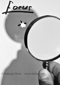
Focus
The magnifying glass is a curved piece of glass we call a lens. Light rays that fall on the lens will be refracted. That means that they will leave the lens traveling in a direction different from where they came from. This change of direction is different for different places on the lens. For rays coming from a very distant source, like the sun, the incoming rays are all in parallel. After passing the lens, they all go through the same spot. This spot – called focal point or focus (f) – is unique for the lens. The focus is related to the curvature of the lens, see the following figure. Note that the light ray going through the center of the lens does not change in direction.
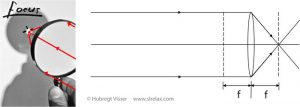
Parallel light rays are entering a lens from the left. After refraction they all pass through the same point. This point is called the focal point (f) of the lens.
We will use this ray tracing or geometric optics concept to explain how lenses function in creating images on a camera’s sensor.
Image Projection
Optics: A lens will flip an image top to bottom and left to right.
Have you ever wondered about the fact that far away objects when seen through a magnifying glass are always flipped upside down (and turned left to right)?
We can explain this “flipping” by using simple optics.
Optics
What we see through the lens we call the image. We may envision the creation of this image as shown in the next figure.
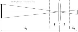
The creation of an image by a lens; Light rays from top, center and bottom of the object travel through the lens to form the image.
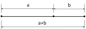
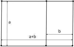
When the object under observation is at a distance S1 from the lens, a sharp image will form – on the other side of the lens – at a distance S2. The two distances S1 and S2 are related to the focal distance f through
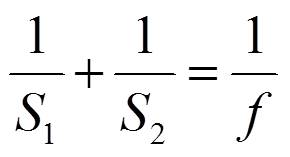
We may construct the image by drawing light rays from the source through the center of the lens to the image position. We see that in this process the image has flipped (upside down and left to right) with respect to the original.
In the Camera
If we place a camera’s sensor (or negative film) at the position of the image, we may capture a (digital) image. After processing (developing) this image, we turn it around to show the picture in the way we want it.
(The enlarged image we see from a magnifying glass is not “flipped”. This has to do with the fact that we place the original at a distance closer than f to the lens. Then the image will form on the same side of the lens, still following the earlier shown thin lens equation. A further explanation is beyond the scope of this post).
In the figure underneath we have placed the lens of the above picture in a camera. The image will project on the camera’s sensor.
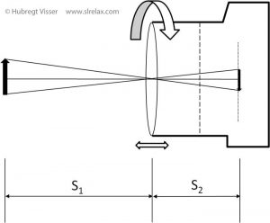
The image created by the lens in a camera is projected on the sensor (or negative film).
The focusing of our camera, manual or in auto-focus, is carried out by (slightly) displacing the lens position. This happens most often by a screw-like motion as envisaged in the figure. The position towards the object we want to photograph is fixed at S1 and so is the focal distance f in this example. This means that we have to adjust S2, i.e. the distance of the lens to the sensor to satisfy the thin lens equation and obtain a sharp image on the sensor.
The thin lens equation also works the other way around. If we know f and S2, the equation tells us the value of S1. That is why we may find a distance indication on the housing of a lens that runs with the focus adjustment.
Focus and Depth Of Field (DOF)
We have described how to obtain a sharp image on the sensor. It came down to adjusting the lens position relative to the sensor plane, given the object we want to have in focus and the focal distance of the lens. But what happens with the image of objects that are not at the location S1 but (slightly) in front of it or behind it? Before explaining these situations we first need to expand our ray-tracing model of lens, object and image.
Light rays
Thereto we look at the rays coming from the top and bottom of the object that pass through the top, center and bottom part of the lens.
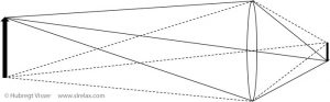
Using ray tracing to construct an image of the object in front of the lens.
The rays coming from the top we represent with solid lines, the rays coming from the bottom we represent with dashed lines. The figure shows how rays passing through the center of the lens are progressing without making a change in direction. The rays at the boundaries of the lens are making the maximum change in direction. The figure also shows that – with the image being in focus – a point from the original transfers to a corresponding point in the image.
Out of focus
Now, we place an additional object in front of the object already present. Given the position of this new (red) object and the fixed focal distance of the lens, a sharp (red) image will occur at the position shown in the figure underneath.
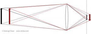
Using ray tracing showing the concept of in and out of focus.
The original object is projected sharply on the camera’s sensor. This is indicated in black in the figure. The sharp image of the red object is projected behind the sensor. We see that points from the original object spread out at the sensor’s position and thus will result in a blurry image. We may use the same reasoning for an object that we place behind the original object that we focus the lens at. For this situation, a sharp image will occur in front of the sensor plane. If we focus at an object, we cal the range before and after this object that is still reasonably sharp in the picture Depth Of Field (DOF).
Increasing the DOF
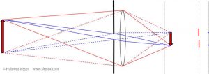
So what can we do to increase the DOF? In the figure above we introduced unsharpness. We have seen that this relates directly to the area over which points will spread out over the sensor. This area depends on the position of an object relative to the object in focus and the size of the lens. Size since refraction will be stronger further away from the center of the lens. Thus, to increase the sharpness we should restrict the lens area that we use, i.e. decrease the aperture size. In the figure underneath we show – in red – the non-focused object of the previous figure. To the right of this ray-tracing figure, we show the blurred projection of the image on the sensor. In blue, the projected image is shown for a restricted aperture. This aperture restriction is indicated with the thick black lines to the left of the lens.
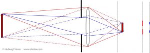
The effect of an aperture on the focus of an image.
Use of Aperture
At the right of the figure above we show how the top and bottom points of the out-of-focus object project on the sensor when we use the full aperture (red). We also show these projections when we limit the aperture in size (blue). We clearly see how decreasing the aperture – i.e. not using the whole lens surface – reduces the blur. As shown in the next figure, where we decrease the aperture even further we see how we can nearly completely compensate this blur.
The effect of a small aperture on the sharpness of an image.
Aperture in numbers
The aperture diameter size is given as a fraction of the focal length, e.g. f/1.4, f/2, f/2.8, f/4, f/5.6, f/8, f/11, etc. This means that a 50mm lens having an aperture f/1.4 uses a diameter of 3.57cm (1,41”). The same lens having an aperture f/11 needs a diameter of 4.55mm ( 0.18”). So the higher the f-number, the smaller the opening or aperture. The sequence of f-numbers shown is such that every f-stop is a factor 1.4 or the square root of 2 times the previous one. The amount of light entering the sensor is for every f-stop a factor 2 times less than the previous one. So, the lower the f-number, the more light is entering. So, for example, a 300mm lens having an aperture size f/1.4 would require a lens diameter of 21.4cm (8.4”). For f/5.6, we only need 5.36cm (2.11”).
In Practice
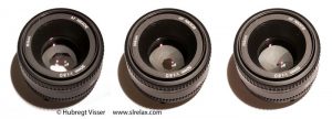
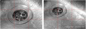
Let’s see how this theory works in practice. Underneath we show three pictures of a match taken with a 50mm lens.
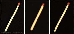
The effect of aperture size on picture sharpness. Left picture: f=50mm, f/4, in focus. Middle: f=50mm, f/4, out of focus/ Right: f=50mm, f/22, out of focus.
For all three pictures we fixed the camera and object positions. The picture on the left we took at f/4 using autofocus. The match is perfectly in focus. For the middle picture we kept the aperture at f/4 but we switched off autofocus. We used manual focus and turned the lens slightly out of focus. The match now looks blurred. For the picture on the right, we kept the lens position the same as for the middle picture but we decreased the aperture size to f/22. Even though we know the match not being in focus, the small aperture produces a sharp image of the match. The picture is not as good as the picture on the left but the compensation by the small aperture for the out of focus image is quite remarkable.
Examples
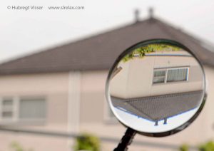
So, now that we understand focus and aperture we can put it in practice. Narrow aperture sizes (large f/-numbers) are used mostly in landscape photography. This is because, as we have just seen, by choosing a small aperture (large f/-number) we can ensure the largest sharpness all over the picture. Using a large aperture (small f/-number) can be used to emphasize an element in your picture since it will ‘blur out’ a distracting background. See the following two examples.

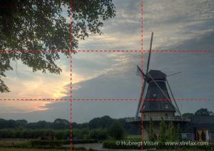
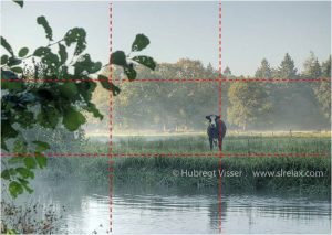
Landscape. Here we need sharpness through the whole picture. f/9, 1/80 sec, iso 100, 40mm.

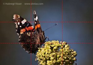
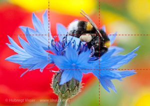
Bumblebee. Here we have used an aperture size small enough to show the bumblebee and flower reasonably sharp, but large enough to ‘blur out’ the flowers in the background. f/4, 1/1000 sec, iso 200, 40mm.
Conclusion
By selecting a certain aperture size we can control how much of our picture will appear to be sharp. We can use this as a creative tool. For example, it can help us to emphasize elements in our picture. We can also use it to ‘blur’ out a distracting background. When we choose a certain aperture size, we need to get the exposure right with the correct shutter speed and/or ISO value.
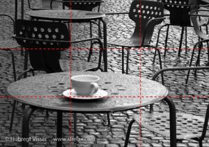
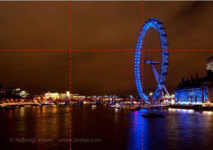
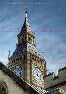
 When you are interested in photography you will start reading books on the subject or browsing the web. Eventually you will encounter the rule of thirds. Or maybe, when playing around with your camera settings, you found this grid you can overlay on your screen or viewfinder. You may have wondered about the use of it. Both have to do with picture composition and creating appealing pictures.
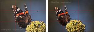


 Photography is all about light. To get the exposure of our picture right, we need to balance the